


Busway
References: R Record keeping requirement | E An engineering/certification requirement | P A permit to work requirement | S A safe work method statement (SWMS) / written plan
Informative
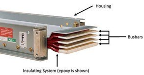
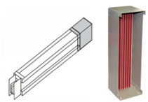
Busway is a prefabricated and modular system designed for the distribution and transportation of electrical energy through a building / structure.
Busway is an alternative to using electrical cables and cable trays etc. Busway requires less space and can be an efficient way to reticulate electricity through a building / structure. Busway is a sealed metal duct that contains either copper or aluminium busways that conduct substantial electrical current. Busway is produced and installed in sections and is joined using bolted, sandwich type connections.
Hazards
Potential hazards include, but are not limited to:
- Falling objects (during installation)
- Electrocution (shock, burns)
- Water/moisture
Design and Planning
R
Building specific design risk assessment must be documented incorporating assessment of potential building movement and include a damage prevention strategy for installation, commissioning, operation and maintenance i.e., for water or other damage.
R A project specific staging plan or similar must be developed for installation, commissioning and energisation.
Busway installation arrangements must provide clearances (between adjacent busway and other services / equipment) as specified by the manufacturer / design risk assessment for inspection, maintenance etc
Risers must be designed to prevent water damage, during construction and operationally.
- Refer to Risers
Expansion fittings must be used in accordance with the manufacturers / design specifications e.g., when installed across expansion joints, lengthy runs where both ends are permanently fixed.
Seismic restraints / bracing in accordance with AS1170.4 must be detailed and installed as per approved shop drawings
Vertical installations must have a minimum ingress protection (IP) rating of 54 (IP54). Horizontal installations should be rated to minimum of IP66.
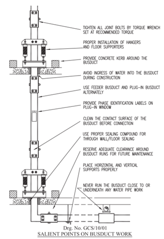
Busways should not run close to or traverse any water pipe, or in the route where it will be affected in case of water pipe leakage/bursting.
Supply, availability and lead times of replacement parts including take off boxes must be discussed with the Supplier to ensure parts can be sourced locally and mitigate risk with lead times.
Warranty terms and conditions must be reviewed.
Storage and Handling
Busway must be handled and stored in accordance with the manufacturer's instructions
The subcontractor providing / installing must inform the Multiplex of all the parameters associated with the storage and installation of busway prior to the initial site delivery.
Storage must be coordinated with Multiplex, Multiplex will allocate appropriate storage area/s.
Busway sections and fittings etc. must be stored in a clean and dry area at all times.
Busway must be handled with care to avoid damage to internal components and the enclosure or its finish.
Installation
Busway must be installed in accordance with the manufacturer’s instructions, and Multiplex Health and safety handbook sections including:
- Electrical – General
- Temporary to Permanent Power
- Work at Heights - General
- Overhead Works Coordination i.e., where working in risers etc.
- Penetrations in Floors
S Prior to the commencement of overhead work activities on projects, SWMSs must be developed by MPX and/or the subcontractor undertaking the works.
People operating cranes or carrying out dogging work must be inducted into applicable SWMS and hold valid records competency / training, evidence must be retained on site. Refer to: Training and Competency Schedule.
Busway joints must be torqued using torque wrench, to manufacturer's specified values and marked prior to energisation.
Busway joint cover plates must be installed sequentially to protect the joint from contamination
Inspection & Test Plans and associated documentation must be completed
Risers
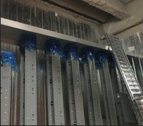
Busway must be protected against water ingress at all times, water damage is a high-risk during installation, temporary protection (bunds, covers etc.), the location and proximity of other risers, etc. must be anticipated in reference to both vertical and horizontal installations
Risk assessments must include:
- Identification of areas where busway (horizontal or vertical installations) / busway risers may be exposed to water ingress. The following must be considered:
- Location / proximity to:
- façade, hoist, crane mast ties/penetrations
- external openings
- Penetrations
- Stairways
- Other services (particularly hydraulic services)
- Rain / wind / storm events
- Dewatering formwork decks / floors
- Temporary / permanent riser walls / baffles (e.g., floor to ceiling)
- Waterproofing etc. and potential for damage to water proofing
Prior to installation of busway, risers and any other potential water exposure points/areas must be protected from water ingress.
Concrete bunds must be installed to prevent water ingress into the riser, bunds must be waterproofed on all sides prior to installation of busway.
Penetration covers must be fully caulked around the perimeter and back to the concrete wall for waterproofing.
Waterproof temporary flashings and busway cap - IP 54 (minimum) must be fitted to the top of the riser / busway.
Riser cupboards must be sealed on each level where Busway is installed (i.e., to further protect against mechanical or water damage).

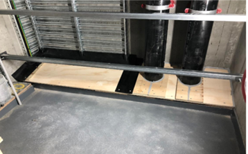
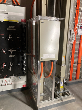
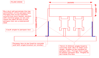
A protection box should be installed as soon as the take-off box connection to the busway has been connected. The box should consist of:
- 5mm Perspex
- Perspex fixed back to the concrete core with the support from 75mm X 200mm aluminium angles.
- All gaps caulked with silicone.
- Waterproof tape to all junctions for additional protection.


Completion and Testing
Busway must:
R Have an insulation resistance test recorded on an ITP and completed:
- On each section of busway once it has been shifted from storage to the final installation location to identify any possible contamination and/or damage during transport and storage prior to installation.
- During construction (10% minimum) to verify that no water or other damage has occurred during the installation process.
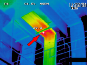
R Have thermographic scans completed to identify any faults, by a person trained in the use of thermographic camera who can analyse scans, provide reports and where require recommend any applicable remedial actions. Thermographic scans must be completed under maximum available load with all components open / uncovered:
- Following energisation and
- During the 12-month Defects Liability Period (DLP) at quarterly intervals (or as agreed) for reviewed against the previous scans.
- Where damage, or faults or deterioration is identified the applicable sections / parts must be replaced / repaired and the warranty validity must be confirmed by the manufacturer / supplier / subcontractor.
- Multiplex should request the manufacturer / supplier complete an inspection following installation completion to confirm warranty validity.
R Thermographic scan results must be distributed to the project consulting electrical engineer for review and sign-off.
R A copy of the valid warranty from the manufacturer must be included in the Operation and Maintenance Manual and Aconex.
Standards
AS ISO 61439.6 - Low-voltage switchgear and control gear assemblies - Busbar trunking systems (busways)
AS1170.4 - Structural design actions. Earthquake actions in Australia
Document Control
Version 1 August 2019 – New Standard for VIC only
Version 9th May 2022 – General amendments incl. requirements for handling and storage and testing.